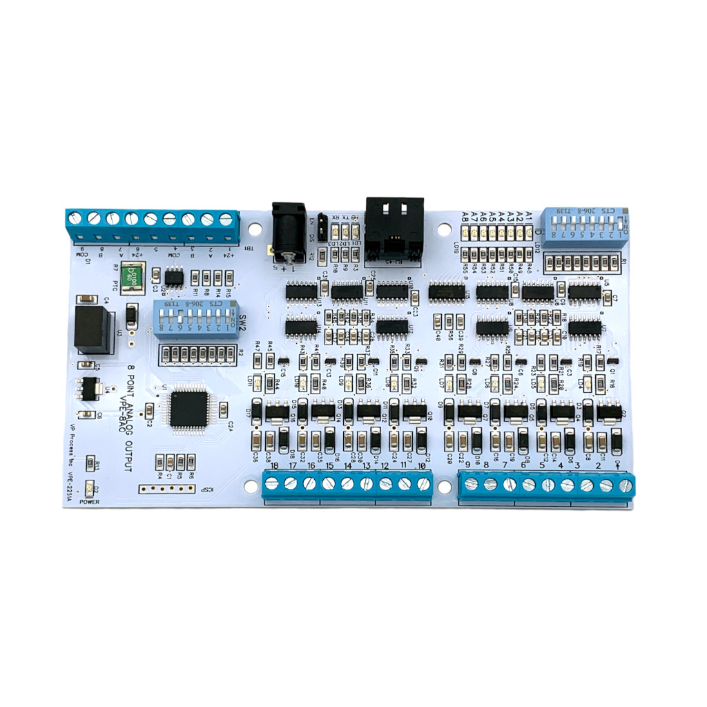
PCB
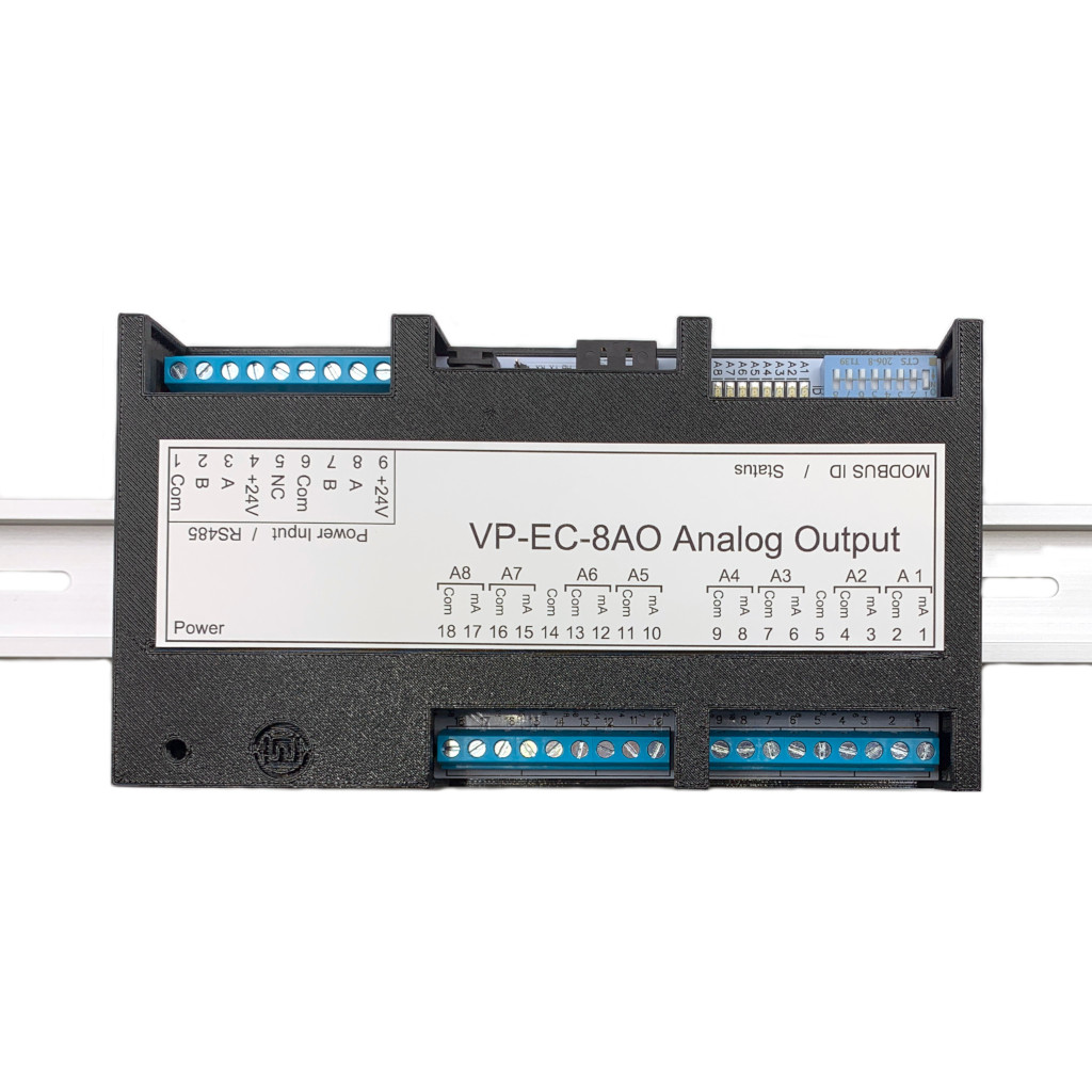
DIN Rail Enclosure
DIN Rail Enclosures are available in Black, Blue and White
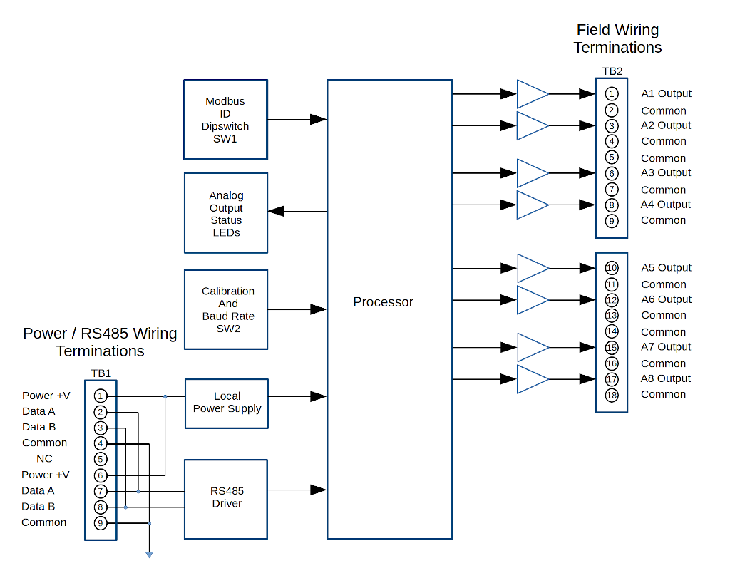
Field Wiring and Block Diagram
Specifications
Modbus Functions and Register List
Calibration
The VP-EC-8AO is an 8 channel analog 0 to 20 mA output module with a Modbus RTU RS485 interface.
DIN Rail Enclosures are available in Black, Blue and White
The VP-EC-8AO Module has 3 different operating modes, depending on the Mode Setting: Dipswitch 2 , SW2-5 and 6. Using Modbus Function 6 (Write Single Holding Register) or 16 (Write Multiple Holding Registers), each analog output can be updated by sending either raw DA Counts, a mA value rangin from 0 to 20.00 mA, or a percentage value ranging from 0% (4.00 mA) to 100% (20.00) mA.
| Mode | SW2-5 | SW2-6 | Description |
|---|---|---|---|
| 0 | OFF | OFF | Software defined Mode Holding Registers 8 thru 15, Channels 1 thru 8 |
| 1 | OFF | ON | 0 to 20 Ma Value sent as 0 to 2000 (2 decimal places) (Factory Default) |
| 2 | ON | OFF | 0 to 100 Percent sent as 0 to 1000 (2 decimal places), 0 - 4.00 mA |
| 3 | ON | ON | Raw DAC Counts sent 0 to 4095 as 0 to 22 mA |
Software defined Mode if SW2-5 and SW2-6 are both OFF. The Mode is selected via the value in the Channel's Mode Holding Register:
| Mode | HR Value | Description |
|---|---|---|
| 0 | 0 | Raw DAC Counts sent 0 to 4095 as 0 to 22 mA |
| 1 | 1 | 0 to 20 Ma Value sent as 0 to 2000 (2 decimal places) (Factory Default) |
| 2 | 2 | 0 to 100 Percent sent as 0 to 1000 (2 decimal places), 0 - 4.00 mA |
Baud Rate Selection is via Dipswitch 2 SW-7 and SW2-8:
| BAUD Rate | SW2-7 | SW2-8 | Description |
|---|---|---|---|
| 9600 | OFF | OFF | (Factory Default) |
| 19.2K | OFF | ON | |
| 57.6K | ON | OFF | |
| 115.2K | ON | ON |
Output Calibration is via Dipswitch 2 SW2-1, SW2-2, SW2-3 and SW2-4. Channel selection to be calibrated is via Dipswitch SW1, the Modus ID switch. Turn all SW1 OFF, and turn on the channel SW to be calibrated.
| SW2-1 | SW2-2 | SW2-3 | SW2-4 | Description |
|---|---|---|---|---|
| OFF | OFF | OFF | OFF | Default Setting, not in Calibration |
| ON | OFF | OFF | OFF | 4 mA Calibrate Mode, Input Channel selected with Dipswitch 1 (ID) 1 thru 8 |
| ON | ON | OFF | OFF | 20 mA Calibrate Mode, Input Channel selected with Dipswitch 1 (ID) 1 thru 8n |
| ON | OFF/ON | ON | OFF | Output Increases in mA while SW2-3 is ON |
| ON | OFF/ON | OFF | ON | Output Decreases in mA while SW204 is ON |
| Item | Metric | Value |
|---|---|---|
| I/O | Part Name : | Channel Analog Output Modbus RTU RS485 Interface |
| Part Number : | VPE-2251 | |
| Channels : | 8 (Source, Referenced to Common) | |
| Output Range (per channel) : | 0 to 20 mA | |
| Over-range limits : | 22 mA | |
| Resolution : | 4096 AD Counts (12 bit) | |
| Accuracy : | +/- 0.1% mA | |
| Sample Rate : | 512 ms Default | |
| Communication | Protocol : | Modbus RTU RS485 |
| Baud Rate | Dipswitch Selectable 9.6K,19.2K, 57.6K, 115.2K (N81) | |
| Modbus ID | 8 Position Dipswitch | |
| Termination | Jumper Selectable Enable or Disable 120 Ohm | |
| Wiring | 2 sets of terminal blocks (+V, Data A, Data B, Common) | |
| Processor | Processor : | PI18F Series |
| Field Connections | Terminal Qty : | 33 |
| Method : | Screw, Rising Cage Clamp | |
| Torque : | 0.753 N-m (4.3 Lb-in) | |
| Screw : | M3 | |
| Voltage Rating : | 300 VAC | |
| Current Rating : | 15 A | |
| Withstanding Voltage : | 1.6 KV | |
| Cross section solid conductor AWG min : | 28 | |
| Cross section solid conductor AWG max : | 12 | |
| Cross section stranded conductor AWG min : | 28 | |
| Cross section stranded conductor AWG max : | 12 | |
| Stripping Length : | 6-7 mm | |
| Physical | Length (DIN Enclosure) : | 6.25" |
| Width (DIN Enclosure) : | 3.6" | |
| Height (DIN Enclosure) : | 2.3" | |
| Weight (DIN Enclosure) : | 150 g | |
| Weight, Shipping (Qty. 1) : | 200 g | |
| Electrical | Power Input Voltage Range (Typical : | 24 VDC |
| Power Input (Minimum) : | 12 VDC | |
| Power Input (Maximum) : | 28 VDC | |
| Current max : | 200 mA (All Channels Sourcing 20 mA) | |
| Current typical : | 75 mA (All Channels Sourcing 4 mA) | |
| Isolation : | None | |
| Ambient | Operating Temperature : | -20 to +65 °C |
| Storage Temperature : | -40 to +85 °C | |
| Operating Relative Humidity (non-condensing) : | 0 to +95 %RH | |
| Storage Relative Humidity (non-condensing) : | 0 to +95 %RH | |
| Protection - DIN Option : | IP20 | |
| Warranty | Limited Liability : | 1 Year |
| Download : | Warranty Statement |
Supported Modbus Functions
| Function | Description |
|---|---|
| Function 03 | Read Holding Registers |
| Function 06 | Write Single Holding Register |
| Function 16 | Write Multiple Holding Registers |
Real Time Output Values (Funtion 3)
| Address (Dec) | Description |
|---|---|
| 0000 | Output Channel 1 Output Value (DAC Counts, mA Value, Percent Value) |
| 0001 | Output Channel 2 Output Value (DAC Counts, mA Value, Percent Value) |
| 0002 | Output Channel 3 Output Value (DAC Counts, mA Value, Percent Value) |
| 0003 | Output Channel 4 Output Value (DAC Counts, mA Value, Percent Value) |
| 0004 | Output Channel 5 Output Value (DAC Counts, mA Value, Percent Value) |
| 0005 | Output Channel 6 Output Value (DAC Counts, mA Value, Percent Value) |
| 0006 | Output Channel 7 Output Value (DAC Counts, mA Value, Percent Value) |
| 0007 | Output Channel 8 Output Value (DAC Counts, mA Value, Percent Value) |
Mode Settings
| Address (Dec) | Description |
|---|---|
| 0008 | Output Channel 1 Mode Setting (0 = Raw DA ,1 = 0 to 20.00 mA (Default), 2 = 0 to 100.0% |
| 0009 | Output Channel 2 Mode Setting (0 = Raw DA ,1 = 0 to 20.00 mA (Default), 2 = 0 to 100.0% |
| 0010 | Output Channel 3 Mode Setting (0 = Raw DA ,1 = 0 to 20.00 mA (Default), 2 = 0 to 100.0% |
| 0011 | Output Channel 4 Mode Setting (0 = Raw DA ,1 = 0 to 20.00 mA (Default), 2 = 0 to 100.0% |
| 0012 | Output Channel 5 Mode Setting (0 = Raw DA ,1 = 0 to 20.00 mA (Default), 2 = 0 to 100.0% |
| 0013 | Output Channel 6 Mode Setting (0 = Raw DA ,1 = 0 to 20.00 mA (Default), 2 = 0 to 100.0% |
| 0014 | Output Channel 7 Mode Setting (0 = Raw DA ,1 = 0 to 20.00 mA (Default), 2 = 0 to 100.0% |
| 0015 | Output Channel 8 Mode Setting (0 = Raw DA ,1 = 0 to 20.00 mA (Default), 2 = 0 to 100.0% |
Fault DA Count Settings - If Real Time DA Counts higher than Fault Setting, Green Channel LED is ON (Default 2.00 mA)
| Address (Dec) | Description |
|---|---|
| 0016 | Output Channel 1 Fault Value DA Counts (Used for Channel Indication) |
| 0017 | Output Channel 2 Fault Value DA Counts (Used for Channel Indication) |
| 0018 | Output Channel 3 Fault Value DA Counts (Used for Channel Indication) |
| 0019 | Output Channel 4 Fault Value DA Counts (Used for Channel Indication) |
| 0020 | Output Channel 5 Fault Value DA Counts (Used for Channel Indication) |
| 0021 | Output Channel 6 Fault Value DA Counts (Used for Channel Indication) |
| 0022 | Output Channel 7 Fault Value DA Counts (Used for Channel Indication) |
| 0023 | Output Channel 8 Fault Value DA Counts (Used for Channel Indication) |
4.00 mA Calibration DA Counts
| Address (Dec) | Description |
|---|---|
| 0024 | Output Channel 1 4.00 mA Value DA Counts (Used for Channel Calibration) |
| 0025 | Output Channel 2 4.00 mA Value DA Counts (Used for Channel Calibration) |
| 0026 | Output Channel 3 4.00 mA Value DA Counts (Used for Channel Calibration) |
| 0027 | Output Channel 4 4.00 mA Value DA Counts (Used for Channel Calibration) |
| 0028 | Output Channel 5 4.00 mA Value DA Counts (Used for Channel Calibration) |
| 0029 | Output Channel 6 4.00 mA Value DA Counts (Used for Channel Calibration) |
| 0030 | Output Channel 7 4.00 mA Value DA Counts (Used for Channel Calibration)) |
| 0031 | Output Channel 8 4.00 mA Value DA Counts (Used for Channel Calibration) |
20.00 mA Calibration DA Counts
| Address (Dec) | Description |
|---|---|
| 0032 | Output Channel 1 20.00 mA Value DA Counts (Used for Channel Calibration) |
| 0033 | Output Channel 2 20.00 mA Value DA Counts (Used for Channel Calibration) |
| 0034 | Output Channel 3 20.00 mA Value DA Counts (Used for Channel Calibration) |
| 0035 | Output Channel 4 20.00 mA Value DA Counts (Used for Channel Calibration) |
| 0036 | Output Channel 5 20.00 mA Value DA Counts (Used for Channel Calibration) |
| 0037 | Output Channel 6 20.00 mA Value DA Counts (Used for Channel Calibration) |
| 0038 | Output Channel 7 20.00 mA Value DA Counts (Used for Channel Calibration)) |
| 0039 | Output Channel 8 20.00 mA Value DA Counts (Used for Channel Calibration) |
Default Power On Analog Output Setting (Depends on Mode Setting)
| Address (Dec) | Description |
|---|---|
| 0040 | Output Channel 1 Power On Default Value (Factory set to 400 for 4.00 mA |
| 0041 | Output Channel 2 Power On Default Value (Factory set to 400 for 4.00 mA |
| 0042 | Output Channel 3 Power On Default Value (Factory set to 400 for 4.00 mA |
| 0043 | Output Channel 4 Power On Default Value (Factory set to 400 for 4.00 mA |
| 0044 | Output Channel 5 Power On Default Value (Factory set to 400 for 4.00 mA |
| 0045 | Output Channel 6 Power On Default Value (Factory set to 400 for 4.00 mA |
| 0046 | Output Channel 7 Power On Default Value (Factory set to 400 for 4.00 mA |
| 0047 | Output Channel 8 Power On Default Value (Factory set to 400 for 4.00 mA |
Dipswitch 2 Value
| Address (Dec) | Description |
|---|---|
| 0048 | Dipswitch SW2 Value - Shows current Dipswitch Settings 0 to 255 (0 to 0xff) |
The Module comes factory calibrated for 4 – 20 mA Output on all 8 Channels